Search

Safety Precautions and Product Model
Safety Precautions
▲ Do not install this equipment in an explosive gas atmosphere, or there will be explosion hazards.
▲ Only qualified individuals should proceed with wiring, or there will be electric shock hazards. Do not conduct any wiring during the system power on to avoid the electric shock..
▲ Do not touch control terminals, internal circuit board and its components, or there will be electric shock hazard.
▲ Earth terminal must be exactly grounded when using inverter. Grounding must be confirmed with the national electric safety regulation and other electric code.
▲ After power off, do not touch internal circuit board or any parts inside within 5 minutes after keypad display went off. Any internal operation must be after making sure of discharge off with instrument checking to avoid the electric shock.
▲ Do not connect AC power to output terminal (U, V, W) of inverter. The only terminal the AC power allowed to be connected is R, S, T (or L1, L2 single--phrase source inverter).
▲ Static electricity on human body can damage MOS device. Do not touch PCB and IGBT without anti-static measure.
▲ Do not lose screws, spacers and other metallic foreign bodies inside the driver to avoid fire hazard and driver damage.
▲ Do not connect 220V AC power to internal control terminal of the driver, or there will be serious damage to the driver.
▲ If overcurrent protection occurs after start the driver, confirm again the external wiring and then power on and run the driver.
▲ Do not switch off the power to stop the driver. Cut off power source after the motor stops running.
▲ Do not install the driver in places with direct sunlight.
VFD Series Type
| Voltage Classes | Rated Power(KW) | Rated Output Current (A) | Adapted Motor (KW) |
| 220V 1-phase | 0.75 | 4.5 | 0.75 |
| 1.5 | 7 | 1.5 | |
| 2.2 | 10 | 2.2 | |
| 380V 3-phase | 0.75 | 2.5 | 0.75 |
| 1.5 | 3.7 | 1.5 | |
| 2.2 | 5.0 | 2.2 |
Technical Index and Specification
| In put | Rated Voltage, Frequency | 3-phase(4T#sereis)380V;50/60HZ 1-phase(2S#series)220V;50/60HZ | ||
| Allowed Voltage Range | 3-phase(4T#series)320V~460V 1-phase(2S#series)160V~260V | |||
| out put | Voltage | 4T#series; 0~460V 2S#series; 0~260V | ||
| frequency | Low frequency mode: 0~300HZ ; High frequency mode: 0~3000HZ | |||
| Overload Capacity | G type: 110% for long-term, 150% for 1 min, 180% for 5s P type: 105% for long-term, 120% for 1 min, 150% for 1s | |||
| Control Mode | V/F control, advanced V/F control, V/F separation control, electric current vector control | |||
| Control Character | Frequency Setting Resolution | Analog Input | 0.1% of maximum output frequency | |
| Digital Setting | 0.01 Hz | |||
| Frequency Precision | Analog Input | Within 0.2% of maximum output frequency | ||
| Digital Setting | Within 0.01% of set output frequency | |||
| V/F Control | V/F Curve (voltage frequency character) | Reference frequency setting 5~600 Hz, multipoint V/F curve setting, or fixed curve of constant torque, low decreasing torque 1, low decreasing torque 2, square torque | ||
| Torque Compensation | Manual setting: 0.0~30% of rated output Automatic compensation: according to output current and motor parameter | |||
| Automatic Current-limiting and Voltage-limiting | During acceleration, deceleration or steady running, detect automatically the current and voltage of motor stator, and control it within bounds based on unique algorithm, minimize fault-trip chance | |||
| Senseless Vector Control | Voltage Frequency Character | Adjust pressure/frequency ratio according to motor parameter and unique algorithm | ||
| Torque Character | Starting torque: 3.0 Hz 150% rated torque (VF control) 0.5 Hz 180% rated torque (SVC, FVC) 0.05 Hz 180% rated torque (VC) Operating speed precision in steady state: ≤±0.5% rated synchronous speed Torque response: ≤50ms VC, SVC, FVC ≤20ms | |||
| Motor Parameter Self- measurement | Being able to detect parameter automatically under static state and dynamic state of motor, thus guarantee an optimum control. | |||
| Current and Voltage Restrain | Current closed-loop control, free from current impact, perfect restrain function of overcurrent and overvoltage | |||
| Undervoltage Restrain during Running | Specially for users with a low or unsteady voltage power grid: even lower than the allowable voltage range, the system can maintain the longest possible operating time based on its unique algorithm and residual energy allocation strategy | |||
| Typical function | Multi-velocity and Traverse Operation | 16 segments programmable multi-velocity control, multiple operation mode. Traverse operation: preset frequency and center frequency adjustable, parameter memory and recovery after power cut. | ||
| PID Control RS485Communi cation | Built-in PID controller (able to preset frequency). Standard configuration RS485 communication function, multiple communication protocol for choice, synchronizing control function. | |||
| Frequency Setting | Analog Input | Direct voltage 0~10V, direct current 0~20mA (optional up limit and lower limit) | ||
| Digital Input | Operation panel setting, RS485 port setting, UP/DW terminal control, or combined with analog input | |||
| Output Signal | Digital Input | 2 channel OC output and one channel relay output (TA, TB, TC), up to 16 choices | ||
| Analog Input | 2 channel analog signal output, output ranging within 0~20mA or 0~10V with flexibly setting, achievable output of physical quantities like set frequency, output frequency | |||
| Automatic Steady-voltage Operation | Dynamic steady state, static steady state, and unsteady voltage for choices to obtain the steadiest operation | |||
| Acceleration and Deceleration | 0.1s~3600min continuous setting, S type and linear type mode for choice | |||
| Time Setting | ||||
| Brake | Dynamic Braking | Dynamic braking initial voltage, backlash voltage and dynamic braking continuous adjustable | ||
| DC Braking | Halt DC braking initial frequency: 0.00~[F0.16] upper limit frequency Braking time: 0.0~100.0s; Braking current: 0.0%~150.0% of rated current | |||
| Flux Restraint | 0~100 0: invalid | |||
| Low Noise Running | Carrier frequency 1.0kHz~16.0kHz continuous adjustable, minimize motor noise | |||
| Speed Tracking and Restart Function | Smooth restart during operation, instantaneous stop and restart | |||
| Counter | A built-in counter, facilitate system integration | |||
| Operation Function | Upper limit and lower limit frequency setting, frequency hopping operation, reversal running restraint, slip frequency compensation, RS485 communication, frequency control of progressive increase and decrease, failure recovery automatically, etc. | |||
| Display | Operation Panel Display | Running State | Output frequency, output current, output voltage, motor speed, set frequency, module temperature, PID setting, feedback, analog input and output. | |
| Alarm | The latest 6 faults record; running parameters record when the latest fault tripping happens including output frequency, set frequency, output current, output voltage, DC voltage4 and module temperature. | |||
| Protective Function | Overcurrent, overvoltage, undervoltage, module fault, electric thermal relay, overheat, short circuit, default phase of input and output, motor parameter adjustment abnormality, internal memory fault, etc. | |||
| Environment | Ambient Temperature | -10℃~+40℃ (please run the VFD in derated capacity when ambient temperature is 40℃ ~50℃) | ||
| Ambient Humidity | 5%~95%RH, without condensing drops | |||
| Surroundings | Indoors (without direct sunlight, corrosive or flammable gas, oil fog and dust) | |||
| Altitude | Running in derated capacity above 1000m, derate 10% for every 1000m rise. | |||
| Structure | Protection Level | IP20 | ||
| Cooling Method | Air cooling with fan control | |||
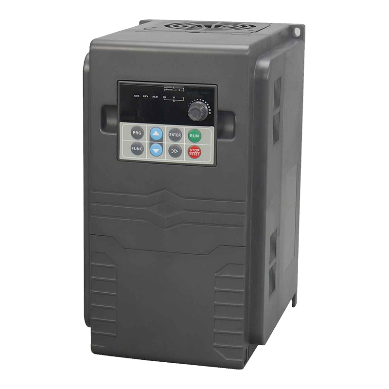
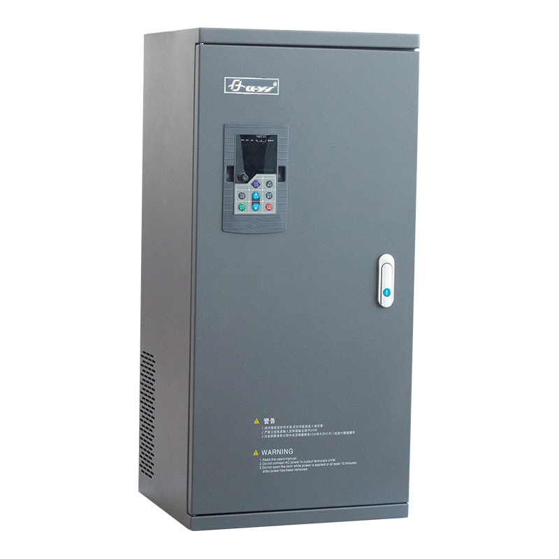
| Installation Method | Wall-hanging type, cabinet type | |||